Marine Hydraulic Steering System Diagram
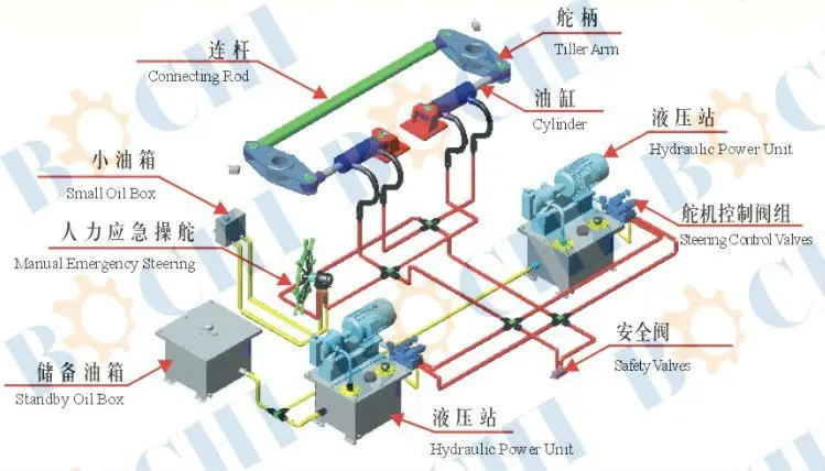
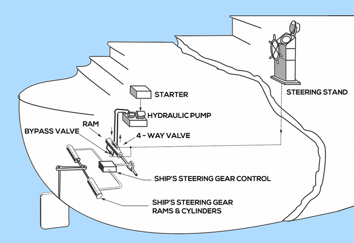
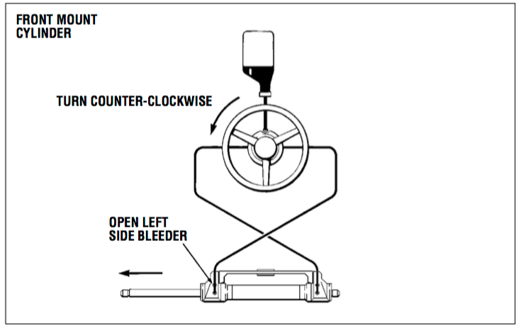
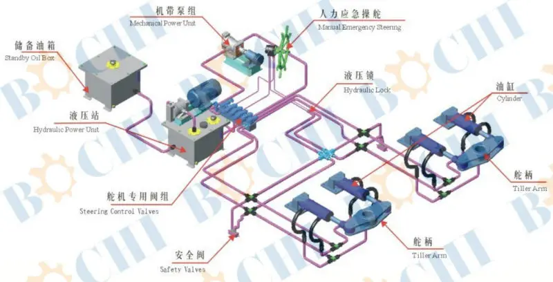
Marine hydraulic steering system diagram. Schematic principles for steering gear hydraulics DNV GL AS The steering gears indicated in Figure 5 and Figure 6 comprises two identical power units and an auxiliary steering gear is not required see subsection 2 and hence the additional requirement for passenger vessels of 70 000 GT and upwards is met for these arrangements. BLEEDING AIR FROM PO WER STEERING SYSTEM Before filling the system with fluid check all hose connections for tightness and proper routing according to the plumbing diagrams referenced below. Here you can find the latest products in different kinds of marine hydraulic steering system diagram.
Electric Power Assisted Steering EPAS System. The most common components in an open hydraulic system on boats are. When we plan Hydraulic Steering Systems for Marine Vessels requiring rudder-torque of more than 200 Kgm due to their higher area of rudder plate or Higher Speed we recommend.
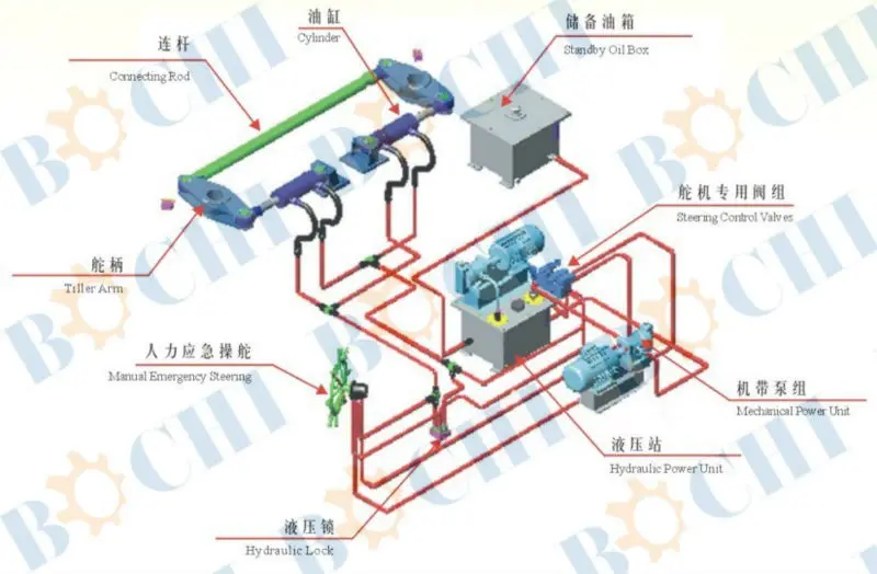
Test each of the joints and flush the system using kerosene or similar to remove the solder flux and scale BEFORE CONNECTING it to the steering unit. Ensure GREY nonvent plug is in use to. The heart of every steering system is the Hydraulic Power Unit.
All hydraulic systems built by Sleipner Motor for our Side-Power systems are open hydraulic systems. It shows the elements of the circuit as streamlined types and likewise the electrical power in addition to signal links in between the gadgets. The HPU must develop the required torque deliver the right rudder speed and degree of travel and perform at a pressure that will maximize the systems components - both hydraulic and mechanical.
A 110 meter b 0 meter c 021 meter v 1 Knots p 0 1x0 -021 00 A 110x0 0 1 meter S 1 x 2 x 0 1 1. We will choose the suitable style for each ship as per requirements from clients. One of the advantages of electric power steering is that it eliminates the power steering pump which can use as much as 8 to 10 horsepower under load.
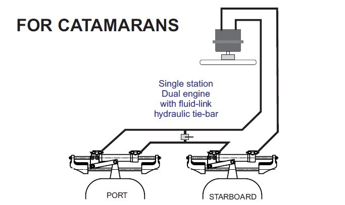
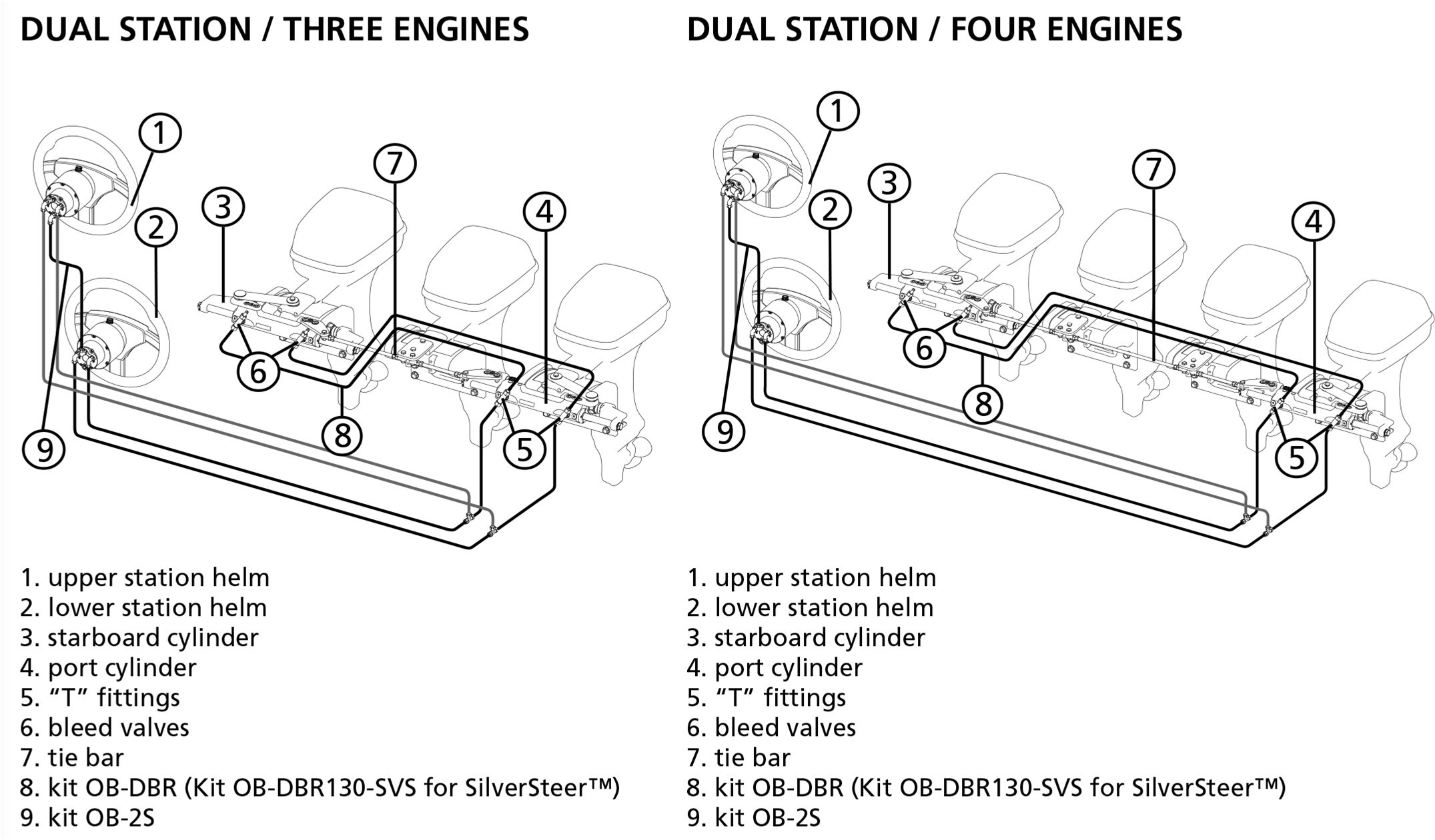
Assortment of marine hydraulic steering system diagram wires diagram. 6 Crafted with CRAFTSMAN MARINE Installation scheme Single steering station diagram Multiple steering station diagram CAUTION. Manual-Hydraulic Steering systems can be used for effort-less drive of Marine Vessels requiring maximum rudder torque of 150-200 Kgm.
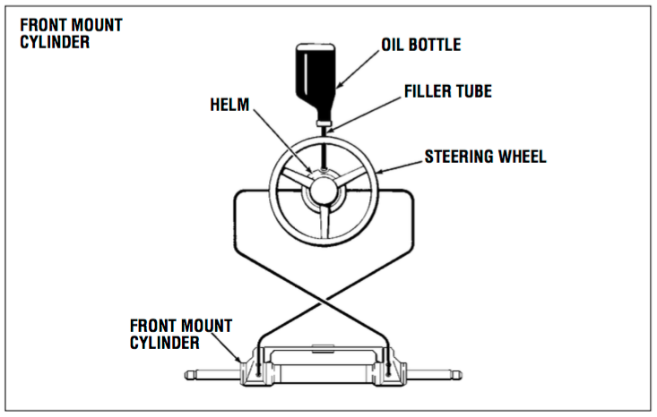
Steering system fill and vent system here seastar nylon tubing or 3 8 copper tubing port line left starboard line right if copper tube is used for general installation use cylinder hose kit here. Full Hydraulic Single BravoSingle Cylinder assembly print drawing 137-9201 Full Hydraulic Single BravoDual Cylinder assembly print drawing 137-9202.
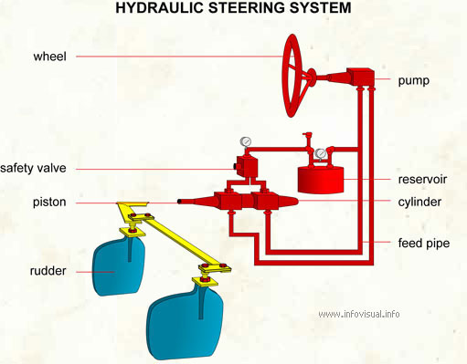
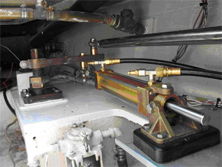
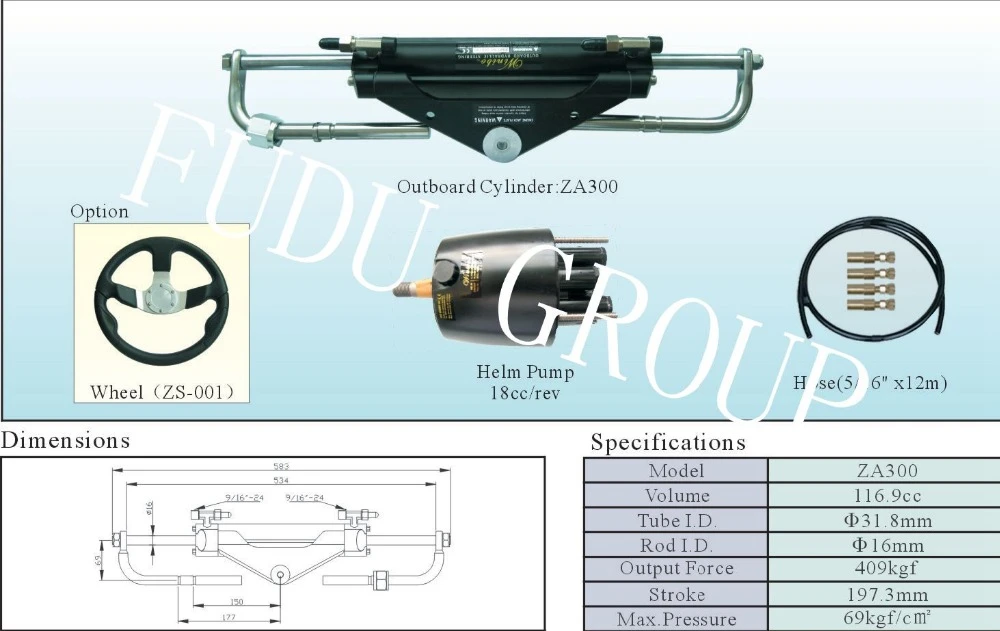
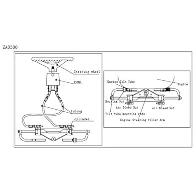
Turning the steering wheel in the direction desired sends an oil flow from the helm pump to the steering cylinder.
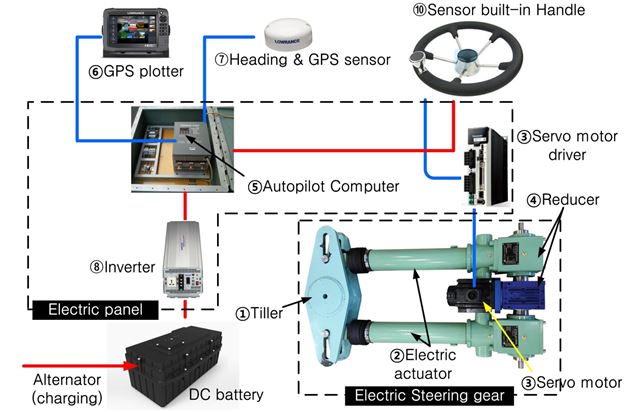
Electric Power Steering EPAS has replaced hydraulic power steering in many new vehicles today. Below is an example of a jog lever steering system complete with provisions with a backup steering wheel Helm Pump. It shows the elements of the circuit as streamlined types and likewise the electrical power in addition to signal links in between the gadgets. 12x00 5631 kgm NOTE. Looking for marine hydraulic steering system diagram. 6 Crafted with CRAFTSMAN MARINE Installation scheme Single steering station diagram Multiple steering station diagram CAUTION. Rudder Propelling Setup Configuration and Installation Dimension. Rod end ball joint tiller arm cylinder mounting foot additional steering station. One of the advantages of electric power steering is that it eliminates the power steering pump which can use as much as 8 to 10 horsepower under load.
Follow steps 4 to 6 in the following section on using Nylon tubing. Ensure GREY nonvent plug is in use to. Rod end ball joint tiller arm cylinder mounting foot additional steering station. This flow which enters the cylinder moves the piston as well as the rod connected to the tiller arm thus causing the rudder to rotate. Compensating line this helm must be fitted with a non-vent plug. The heart of every steering system is the Hydraulic Power Unit. Rudder Propelling Setup Configuration and Installation Dimension.









Post a Comment for "Marine Hydraulic Steering System Diagram"